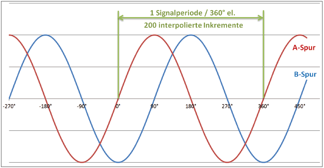
An incremental encoder with 1 Vpp - Interface provides two sine waves, each as a differential output signal. The phase shift between these is 90°. One signal period (i.e. 360°) relates to one incremental division of the encoder. The Irinos-Box EC-INC separates a division into 200 incremental steps via analogue interpolation. Thereby the usable resolution of the encoder increases by 200.
Example: An incremental encoder has a resolution of 1.800 divisions/revolution. Via the interpolation, this results in
1.800 divisions/revolution * 200 increments/division = 360.000 increments/revolution.

1Vpp signal period
The accuracy and reliability of the interpolations depends on the quality of the differential sine signals. An ideal signal has the following characteristics:
oThe differential voltage is 1 Vpp.
oThe signal offset is 0, i.e. at 0° the signal always provides the same value.
oThe phase shift between both sine signals is exactly 90°.
In reality, such a signal is rarely available. Because of this, the Irinos-Box EC-INC has an integrated gain- and offset control (patent applies). It corrects these deviations within the allowed value range (see limiting values in the specification section of the datasheet).
Below or above the threshold values, a reliable interpolation is not possible. An integrated signal examination detects such errors. The error status can be read by software in parallel to the measurement. In case of an error, the counter channel should be reset. The referencing procedure should be redone.
Signal quality
The signal quality depends on various factors. Important ones are:
oSpeed of the incremental encoder
The higher the speed of the incremental encoder, the smaller the actual differential voltage. Some incremental encoders have a very good signal quality while standing still or at low speed. As soon as they are moved / turned, the signal quality decreases rapidly.
oMechanical stability of the incremental encoder and the mechanics
An incremental encoder or a measurement device, which does not move smoothly, leads to variations in the measurement signal.
oAdjustment of the incremental encoder
Some incremental encoders (e.g. glass scales) need to be adjusted. An improper adjustment can lead to an insufficient sensor signal (especially for dynamic movements).
oCable length and cable quality
The longer the cable, the worse the signal quality.
The more connectors are used, the worse the signal quality.
A cable with insufficient shielding or wrong line impedance deteriorates the signal quality.
Often the reason for a signal problem is a combination of these factors.
Suggestions
oPlease observe the cut-off frequency of the incremental encoder. It can be found in the encoder datasheet.
Attention: The cut-off frequency depends on the cable length.
oCheck the signal quality during system setup. The signal levels should have enough margin to the limits.
The Irinos-Tool provides a live-view of the signal levels.
oMake sure that no strong jerk can disturb the signal quality.
oBe prepared to enhance the measurement procedure by the functionalities "reset encoder error" and "restart referencing".
oUse short cables with sufficient shielding (this also applies to the connectors). Avoid extension cables. The Irinos-System allows placing the Irinos-Box next to the incremental encoder.
oKeep distance between the incremental encoder cable and possible sources of noise, like for example frequency changers or motor cables.